Understanding a Process Control Loop
https://instrumentationtools.blogspot.com/2015/06/Understanding-Process-Control-Loop.html
Hi, its me again and I am about to tackle a very important framework in the field of Instrumentation. Assuming you already have read my post regarding what a process control is and what are the parameters involved in this process. We are now going to learn how these parameters are meet in a process control loop.
First we need to know what are the major components a traditional control loop has.
1. The controller
2. a sensor/transmitter
3. a final control element
 |
| Closed Loop Controller Animation |
A controller that seeks to maintain the measured process variable (PV) transmitted by a sensor or a transmitter. and a the final control element that implements in real life the decision or solution taken by the controller. Common examples of a final control element are control valves, relay switches and variable frequency drive to name a few.
To design and implement a controller, we must: have identified a process variable we seek to regulate (e.g., room temperature like in the example mentioned), be able to measure it with a sensor, and be able to transmit that measurement as an electrical signal back to our controller, and have a final control element that can receive the controller output (CO) signal, react in some fashion to impact the process (e.g., a control valve moves or a relay switch turns on/off), and as a result cause the process variable to respond in a consistent and predictable fashion.
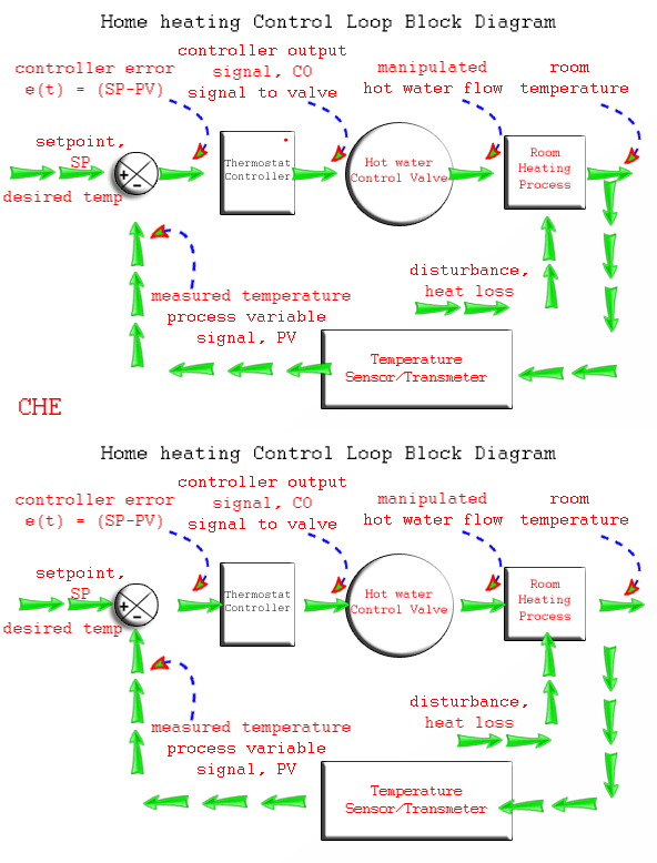
As shown below Animation, the home heating control system described by wiki can be organized as a traditional control loop block diagram. Block diagrams help us visualize the components of a loop and see how the pieces are connected.
 |
| Closed Loop System Working Animation |
A home heating system can be a simple on/off control or a proportional control by adjusting the amount of hot fluid by throttling a control valve. Nevertheless, we introduce the idea of control loop diagrams by presenting a home heating system in the same way we would a more sophisticated commercial control application.
Starting from the far right in the diagram above, our process variable of interest is the house temperature. A temperature sensor, such as a thermistor in a modern digital thermostat, measures temperature and transmits a signal to the controller.
The measured temperature PV signal is subtracted from set point to compute controller error, e(t) = SP – PV. The action of the controller is based on this error, e(t).
In this example,home heating system, the controller output feds a varying or proportional milliamp signal to a variable operating solenoid or servo valve (our Final Control Element)that controls the flow of hot water .
As the energy output of the furnace rises or falls, the temperature of our house increases or decreases and a feedback loop is complete.
The important elements of a home heating control system can be organized like any commercial application:
Control Objective: maintain room temperature at (SP) in spite of disturbances
Process Variable: room temperature
Measurement Sensor: temperature sensor,Thermistor
Measured Process Variable (PV) Signal: signal transmitted from the thermistor
Set Point (SP): desired room temperature
Controller Output (CO) or Manipulated Variable (MV): signal to the variable operating solenoid valve.
Final Control Element (FCE): variable operating solenoid valve to control hot water flow
Manipulated Variable: hot water flow rate to chamber
Disturbances (D): heat loss from doors, walls and windows; changing outdoor temperature; sunrise and sunset; rain…
With the loop closed as shown in the diagrams, we are said to be in automatic mode and the controller is making all adjustments to the Final Control Element. If we were to open the loop and switch to manual mode, then we would be able to issue controller output commands through buttons or a keyboard directly to the Final Control Element. Therefore:
Open Loop = Manual Mode
Closed Loop = Automatic Mode
This control loop block diagram will be a frame work to more simple process control and even to more sophisticated commercial control application. I hope you learned something. jump in to more of my posts.
Also Read : How to Tune a Process Control Loop

Outstanding & Simple Explanation.
ReplyDelete